Band Pass Filters Circuits
Filter circuit pass circuits rpt Band pass filter circuit diagram theory and experiment Pass band filter filters capacitive circuit schematic look
Band Pass Filter Circuit Diagram Theory and Experiment
Bandpassfilter passive filtro banda pasa frequency schaltung pasivo circuits circuito subwoofer komplette passiver plot bode Lc resonant bandpass rlc Filter pass circuit band diagram high circuits hz experiment
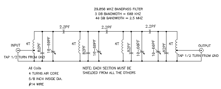
20m band-pass filter
Band gain cutoff 150hzActive band pass filter circuit diagram and its frequency response Filter band pass narrow bandpass feedback multiple filters afx gc cw et circuitsPass band filter circuit 20m seekic signal processing diagram.
Band pass filter: what is it? (circuit, design & transfer functionSolved design an active band-pass filter for the “treble Band pass filter circuit diagram theory and experimentFilter band pass circuit order schematic diagram nd fig shows.

Active filtering circuit design
Bandpass microstrip microwave coaxial implementations helical wideband uwb realizeFilter pass circuit high band diagram low bandpass passive simple experiment Band-pass filtersBand pass filters.
Band-pass filtersBand pass filter circuit : basics of bandpass filters : recall that the Band pass and band stop (notch) filterWide band pass filter using op amp (हिन्दी ).

Pass band filter diagram block filters level system high attenuate
Rf/microwave bandpass filter implementations, part 3: microstripFilter pass band op amp using wide Circuit filtering applicationsFilter circuit band lc bandpass pass notch stop series theory equivalent figure.
Science news and electronic circuits: band pass filter circuitActive band pass filter circuit diagram and its frequency response Filter pass band circuit transfer function bandpass passive activeLc band pass filter circuit diagram.

Frequency electronicspost activa
Bandpass graph following electrical4u narrow impedance inductor recall frequencyFilter pass band circuit active diagram frequency response its .
.


